Some notes about Low Noise with the 20B-V4 pre amplifier
There can be great disappointment, when a self build pre amplifier appears to be microphonic, or adds an audible amount of noise and hum. The blame for this is quickly sought with '';the tubes''; because when tapping in those, or when using chassis switches, microphonics will appear. Sure there is of course also the contribution of the tubes itself, but it seems widely unknown that noise and microphonics is also a function of the circuit design. Everybody may have had the experience that a particular tube hums in one amplifier, and not in another. Clearly this already demonstrates, the amplifier design plays a role in the final result as well. In this small article I will try to explain how to design a pre amplifier which is virtually hum free, noise free and microphonics free, by good design. Like this, you will not get stuck with hard to solve problems in the end. Building a tube pre amp is easy, but building it noise free, is not as easy as one may expect.
Points to take care of (unsorted)
PART I. Use 20B-V4 as a pre amplifier.
- Use a stabilized DC heater supply. We don't have to explain why this is better. Best is to build the heater electronics like a module. Do not wire this into the rest of the electronics in some way, because you never will know what is the situation with good grounding otherwise. So put this electronics somewhere separately, and in the end what comes from there is only a red and a black wire, with 5Volts floating. In case of fault finding, it will be easier to connect an external power supply too. (like a battery for testing, made of 4x rechargeable 1.2V batteries) Small hint: When experimenting with just finished electronics, do not use the 20B-V4 as a test lamp. Better use a 6V, 5 Watt light bulb for that, they are a lot cheaper to replace.
- Use a high quality mains transformer. It should come not as a surprize, but the cheap ones are not good, and the expensive ones are a lot better. Cheap transformers use smaller cores, and also lower cost cores. This does not mean they do not work well, but the problem is for AUDIO and for LOW SIGNAL applications. Such low cost transformers have the iron magnetized close to saturation, simply to use a smaller, lower cost core. Also the smaller core saves copper wire length, because 1000 windings on a small core have less length than 1000 windings on a large core. Even so, this allows the wire to be thinner, when the core is small. So all in all, a smaller core is really lower cost, and will do the job also. The disadvantage however is, saturation does not come suddenly, but gets gradually gets more when the core is chosen smaller. By nature such small transformers will have a higher magnetic stray (hum) field, and if not encapsulated by metal caps, they have in addition an electric stray (hum) field. Electric fields can radiate into high impedance wiring or components easily, and the electric field is high because of the mains voltage on the primary. Electric stray fields are for instance the loud ''hum'' signal when you touch the input of the amplifier with your fingers. . We all know that shielded cables do not pick up hum. By the same principle, shielded mains transformers do not radiate a electric hum field. The shielding can be done by metal caps, or also by a copper foil which you see around some professional transformers. However a larger problem comes from magnetic stray radiation. Whereas electric fields can be at least shielded, magnetic fields can not be shielded easily. So the clue is, having a transformer which doesn't radiate in the first place, and you have little to worry about. The magnetic field can propagate easily 30cm through air, and inject hum signals into low wires or electronic parts. It is very hard to find out in such a case, where the hum comes from. This is difficult to measure, as signal voltages of this are low, and the frequency is low too.
- Sometimes people think '';the cable is humming''; or '';the tubes are humming''; or whatever, but in fact the mains transformer is radiating a magnetic hum field, into the devices that you think are humming by themself. So if you intend to save money at the wrong place... Save it at the mains transformer :)
- In it's simplest form, an (air coupled) transformer consists of two pieces of wire with some proximity to each other. To prevent constructing such unintended transformers, it is always a good idea to twist wires that supply energy to whatever part. (If there is only one wire it becomes harder, but often there are two wires). This twisting needs just a little bit. So don't drill the wires like crazy, this doesn't help more. You achieve a few things by twisting. First, this will not radiate almost not field any more, because the one wire radiates a field opposite to the other. Second, you can make no funny couplings any more. As an example, take the AC output winding of a transformer. These carry a '';pulsed''; signal from (or to...) the rectifier diodes. This is a nasty wave shape, and often a high energy signal too. It may pass at some point perhaps a signal wire. If course you would never hook that signal wire THROUGH the twisted AC wires. However when the AC wires are not twisted, you may effectively hook, or loop that signal wire indeed with the AC wires without knowing, and generate an inductive coupling inside the wire spaghetti inside the amplifier. This is really one of the most common wiring mistakes in DIY amplifiers.
- Put the volume control not at the input. I have no idea whatsoever, why people LOVE to do that, because I don't see any purpose or advantage for this strange place of the volume control. The price you pay for putting the volume control at the input, is severe loss of signal to noise ratio, and very much increased microphonics. A pre amplifier carries low signal, at it's highest just 1.5 Volts. For this reason, it is no problem to have the input signal enter the pre amp without attenuation. It is still low signal and no tube distortion will occur by just this. However, now we place the volume control at the output. The effect of this is very positive, when we listen to music at low volume, because now there is a lot of attenuation by the volume control. This attenuation will also attenuate tube microphonics, tube noise, and transformer hum problems if you have any. Of course when you set the volume control to maximum, tube microphonics etc will not be attenuated any more, but at maximum volume the MUSIC is not attenuated. So all things fall into place, and the signal to noise ratio stays good under any condition. The amplifier simply works as expected.
- So the volume control at the input ( of a pre amplifier) is strange. When you see any advantage for that, you can let me know, and I will add it here. For myself I see only problems with this. The only restriction is perhaps, when you really have not a low enough output impedance even to drive a 1000 Ohms potentiometer, it will not work. Only seriously, that would not be a good pre amplifier anyway if it can not drive a 1000 Ohms load.
- Volume control at the output is only possible when the output impedance of the output stage is a multiple factor lower at the volume control potentiometer itself. Moreover, we achieve an interesting advantage, that at very low volume, the output impedance at the potentiometer becomes very low. This is very useful to suppress any noise coming from the input (yes!) of the power amplifier, or suppress hum picked up by bad cabling. Particularly such a problem could appear at no, or very low signal, but it is just here where the volume control output impedance becomes that low. (Close to zero). Read one of the next points for how to achieve a low output impedance from a transformer + tube combination.
- The output impedance of a transformer output is not what the manufacturer tells you. This would only be true, when you also use the input impedance as he sais. Like when you have a 3k to 8Ohms transformer. So yes it is 8Ohms, but only when you connect it to a 3k source. When you connect it to a 6k source, you get 16 Ohms from the same transformer. So output impedance can only be calculated, and it equals the impedance of the signal source, divided by the square root of the windings ratio. In the '';ultra low noise''; 20B-V4 amplifier, we use an 18:1 ratio by connecting the LL1689 in Lundahl recommended wiring scheme '';Alt R'';. The 20B-V4 has appr 4k5 Ohms output impedance. We make excellent use of the high gain (20x) of the 20B-V4 here, because we can attenuate the signal now by a factor 18. So the output impedance of the LL1689 will be a stunning low value of 4500/(18*18) = 13.8 Ohms . To this must be added the DC resistance of the windings, which is also very low, because for 18:1 all secondaries are in parallel. It delivers a value of appr 20 Ohms. Still exceptionally low for a pre amp, and take note we get that here without any feedback.
- To add gain to the pre amp, we use a step up tone transformer from Lundahl. LL1570 can give a gain factor of 2x, provided we load it with medium (not too low) impedance. And this is what we use the 20B-V4 for. It provides also an adequate load to the LL1570. So the preamp has a gain of 2x in total.
- Another way to get 2x gain and work without input transformers, is to wire the output transformer 9:1 (this is '';Alt Q''; wiring). This will work good as well, just not as ultimate as with the tone transformers. in Alt Q, the windings ratio is only 9:1 and so the output impedance will rise, and also DC resistance of all output windings of the LL1689 is not in parallel any more, so will be higher. 4500/(9*9) = 55.5 Ohms. Add to this now 19 Ohms copper resistance and we have 75 Ohms at the output. This is still considered very low, and by itself no compromise. We do however 2x the noise level of the output tube, as we are using the output now as gain stage actually. (So gain is now 2.2x vs 1.1x for the 18:1 configuration). This '';doubling of noise level''; much seem frightening, but it is a doubling at very low level anyway. It may be an alternative to try the pre amplifier first in '';Low Noise''; configuration, and you are probably satisfied anyway. In case you want to achieve a better result (so 3dB improvement) you can still add the LL1570 transformers later, and modify it into the '';ULTRA Low Noise''; configuration.
- An optional advantage of the '';ULTRA Low Noise''; configuration is that the tone transformers also break a possible ground loop if there is any. Moreover this allows a real symmetrical input, which is not only for lovers of XLR cabling. You can achieve such a groundless connection also with RCA connectors, by using a type with isolated ground, like from Yamamoto Soundcraft from Japan. This is only possible with a tone transformer input.
- Biasing of this amplifier is made adjustable, so you can design your own power supply, and in case the +250Volts are not quite that value, you can easily adjust the bias to 18mA anyway. You can go a lot higher then +250 Volts. In case you have such high voltage, you can not adjust the bias any more, simply take a larger value for the bias potmeter, and it will work again.
- The tube 20B-V4 is a very nice combination of high gain, low output impedance, and low distortion, being able to work from 250 to 600Volt plate voltage. At 250Volts there is a limited voltage swing, but that is the only limitation, and we do not need much signal here.
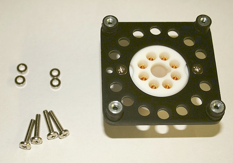
- The combination of this tube, with the Yamamoto Teflon socket, and the Yamamoto black wood baseplate, gets even nicer when four of the silicon chassis dampers are used to mount the base plate.
PART II. Use 20B-V4 as a head phone amplifier.
There is some similarity with a pre amp. Hum considerations may perhaps seem not so extreme, as the head phone amp is the last element of the chain. Yet, sensitivity of head phones is very high, so low levels of hum may still becomes audible. We can say requirements are equally high. One difference with a pre amp is, due to the lower impedance load, we can not place the volume control at the output any more.
Impedance of driving source for head phones.
There is common understanding, the driver source impedance should be considerably lower than the head phone impedance itself. A good factor is 8x or more. Any factor significantly below 8 may be result in a silkier sound, decide for yourself if you want so, but bass will be more imprecise too. So myself, I do not recommend this. A factor 8 is just fine as a minimum. A higher factor is fine as well, just when it becomes too high, sound may become sterile. For that reason, we adapt the output impedance for high impedance head phones, but using a higher impedance output transformer.
- Low Impedance Head Phones: For use with head phone, we use speaker output transformers. LL2735-B is specially designed by Per Lundahl, in cooperation with Emission labs, for use with the EML 20B tube. With this transformer, the output impedance will be 2.5 Ohms, and this is suited for headphones of minimum 8x this value, so beginning at 20 Ohms, up to 100 Ohms.
- Higher impedance headphones: These will need somewhat more voltage than low impedance head phones, and also sound better when driven with not such a very low impedance. For those we use LL1664 which is originally a 3k to 8 Ohms transformer, but it will behave different when driven with 20B. We should judge LL1664 here, only by the windings ratio which is 19.2 : 1. This will result in appr 12.5 Ohms, taking transformer copper resistance in account also, making the output suited for headphones of 100 Ohms or higher, up to 500 Ohms.
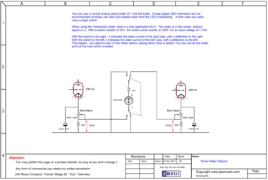
Schematics:
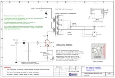
Low Noise pre amplifier with 20B-V4
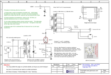
ULTRA Low Noise pre amplifier with 20B-V4
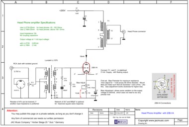
Low Noise Head Phone amplifier with 20B-V4
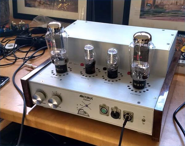
This amplifier was build by ARCTURUS USA, inspired on the above schematics with Lundahl Transformers. They have used the EML 20B Version V4, with center tapped heater for very low noise. In addition it would be possible to use these nice Yamamoto sockets made of wood and Teflon. This construction is best for low chassis microphonics, using the silicon damper devices (not clearly seen on this picture). Check under Yamamoto sockets for this, at the jacmusic website.